Diagnostic modes.
Diagnostics are run at constant delay time, usually with the pump pulse arriving after the probe pulse. Their purpose is to check the performance of the system on shot-to-shot bases, and to adjust amplifier gain, gate levels and other characteristics. Four types of diagnostics have been implemented:
| PD2 vs PD3 (Is vs Ir) |
|
to monitor linearity between sample and reference channels. |
| PDs vs time |
|
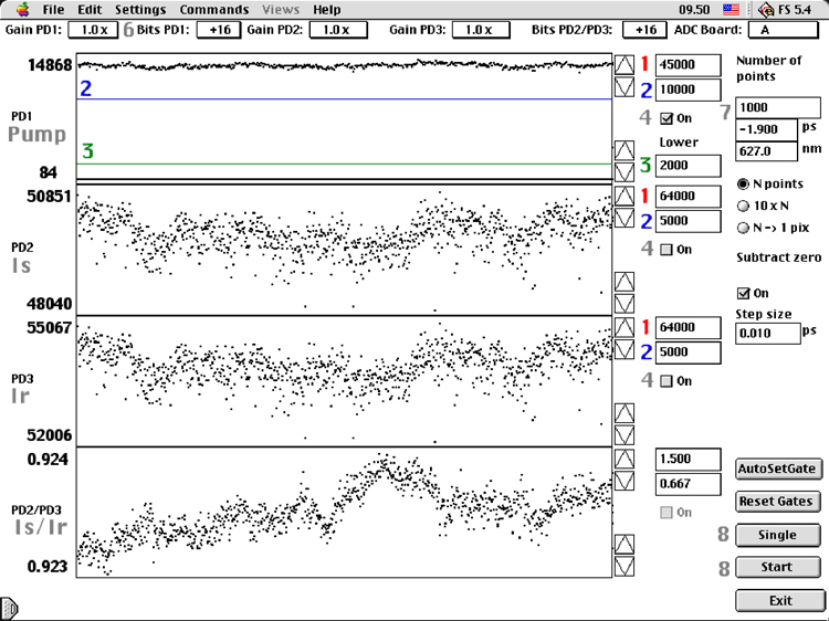
to monitor signal levels (I) from the photodiodes (PD). Fig 1. |
| ∆Abs vs time |
|
to monitor the distribution of individual ∆abs measurements. |
| DiodeArray |
|
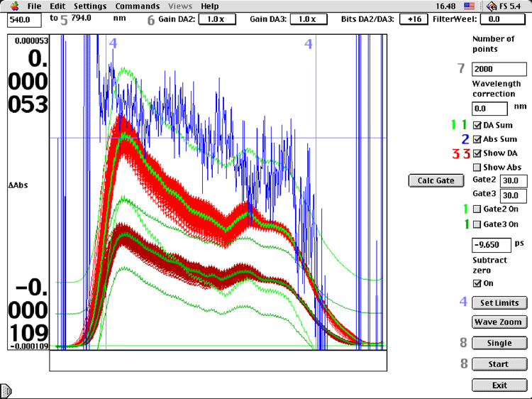
to monitor the signal levels and ∆abs of the diode array. Fig 2. |

1) PDs vs time diagnostics. 1: Upper gate level; 2: Lower gate level; 3: Chopped pump gate level; 4: Gate on/off; 6: Digitizer options; 7: Number of collected points; 8: Collect single or repetitive.

2) Diode array diagnostics 1: Averaged intensity & gate levels; 2: Averaged absorption; 3: All 2000 individual intensities; 4: Limits for scaling of ∆Abs; 5: Wavelength range; 6,7,8: See fig 1.
|


